I designed an operational transconductance amplifier (OTA) for an oscilloscope probe, implemented in a TSMC 0.25 µm CMOS process, used to buffer on-chip signals when they are routed off-chip for measurement.
The amplifier was required to have a closed loop gain of 10 V/V, enable DC voltage measurements within 1% accuracy and less than 1% overshoot, all while maintaining thermal noise below 30µV and consuming no more than 900µA of current.
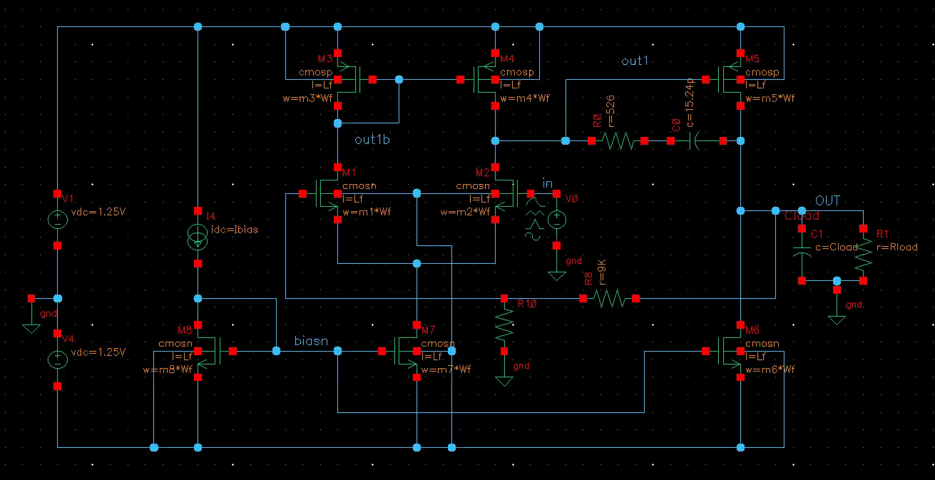
Starting from hand calculations, I sized the input differential pair, current mirrors, tail current sources, and second-stage driver to establish the required transconductance, output resistance, allocating more current to the second stage as it drives the output.
The main challenge in this project was balancing stability and speed while driving a large 20 pF load. To address this, I iteratively tuned transistor width ratios and bias currents using DC operating-point simulations to ensure all devices remained in saturation while extracting transconductance, output resistance, and overdrive voltages.
Next, I performed AC and stability analyses using Cadence Spectre to extract loop gain, phase margin, unity-gain frequency, and closed-loop bandwidth. During this process, I utilized Miller compensation and Miller Zero Removal to ensure a large phase margin under feedback while driving the 20 pF load. I then ran transient simulations across multiple step amplitudes to evaluate settling time and overshoot to ensure my design met spec.
Finally, I analyzed robustness across temperature, supply-voltage, and load corners. I computed integrated input-referred noise using extracted transconductance and simulated closed-loop bandwidth, and verified performance degradation trends through temperature and supply sweeps to ensure the design remained compliant under worst-case conditions.
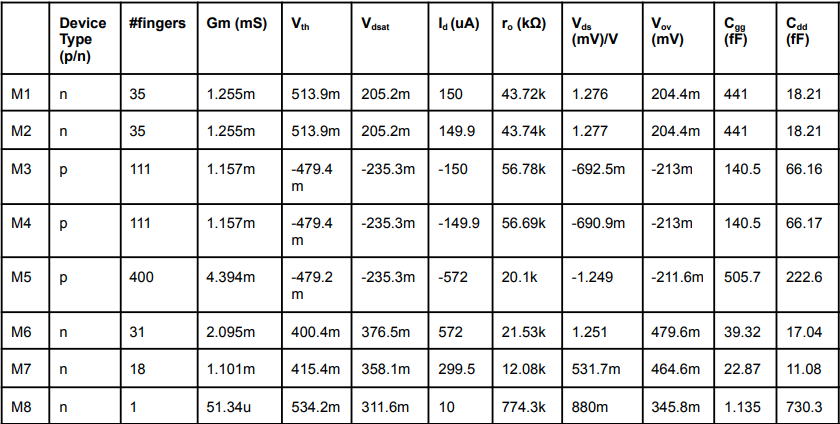
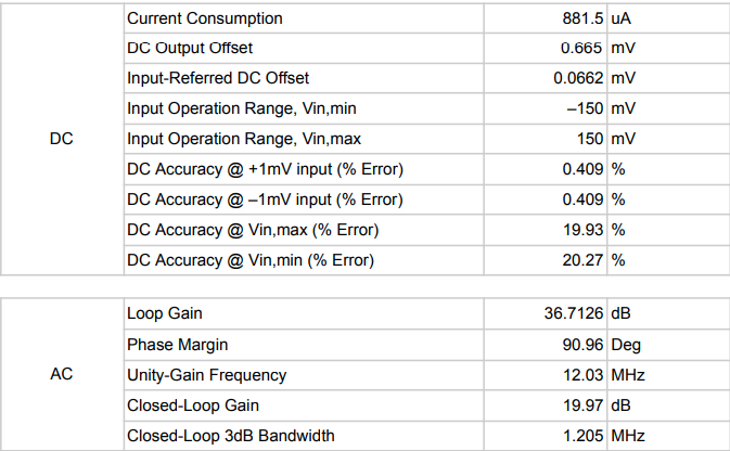
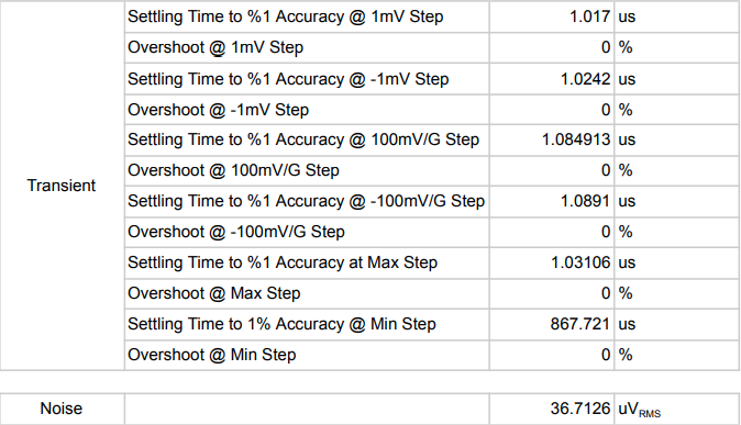
The final OTA met all required performance specifications under nominal operating conditions. The design achieved a closed-loop gain of approximately 10 V/V with a unity-gain frequency of 12.03 MHz and a closed-loop bandwidth of 1.205 MHz while driving a 20 pF load. Stability was ensured with a phase margin of approximately 91°, resulting in fast, well-damped transient behavior.
Power and accuracy targets were satisfied, with total current consumption of 881.5 µA and an input-referred DC offset of 66.2 µV. Transient simulations showed approximately 1 µs settling time to 1% accuracy with 0% overshoot. Integrated noise performance exceeded requirements, with a room-temperature noise of 5.77 µV, providing substantial margin below the 30 µV specification.